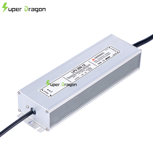
The electrical current that reaches buildings and industries has certain characteristics.
The majority of receivers that are connected to the electrical network cannot work directly with this current, it is necessary to modify it.
The electrical network supplies alternating current, which reverses its polarity about 100 or 120 times per second, depending on the standard followed in each country.
The electronic equipment working with direct current, which has a fixed value, always with the same polarity.
To convert alternating current into direct current it is necessary to rectify and stabilize it.
The voltage of the electrical network can be between 110V and 400V, depending on the country.
The connected equipment can work at any voltage, depending on its application. For example, a television works internally with various voltages, which can range from little more than 1Vdc to more than 50000V in the case of CRT televisions (cathode ray tube televisions, which have already been replaced by flat screens).
The most basic example of a power supply that we all know would be the charger for the mobile (cell) phone.
How a Switching Power Supply Works
To understand the operation of a switched source, we must separate it into blocks, and analyze them step by step.

Let’s get started!
There are many different types of sources, and it would be impossible to explain the details of each.
Therefore, I have believed that it is best to focus on the most common systems.
Blocks of a Switch Mode Power Supply (SMPS)
Common blocks or sections in switched power supplies
EMC filter. Its function is to absorb the electrical problems of the network, such as noise, harmonics, transients, etc. It also prevents the source itself from sending interference to the network.
Rectifier Bridge. It only lets the current pass in one direction, so that it converts the alternating current into pulsating current, that is, it oscillates the same as the alternating current, but only in one direction.
Power factor corrector. In certain circumstances, the current is out of phase with respect to the voltage, which causes that all the power of the network is not used. The corrector is responsible for solving this problem.
Condenser. Dampens the pulsating current to convert it to direct current with a stable value.
Transistor. It is responsible for cutting and activating the passage of current. In this way direct current is converted into pulsating current.
Controller. Turns the transistor on and off. This part of the circuit usually has several functions, such as protection against short circuits, overloads, overvoltage ... It also controls the power factor correction circuit. In addition, it measures the output voltage of the source, and modifies the signal delivered to the transistor, to regulate the voltage and keep the output stable.
Transformer. It reduces the voltage, and also physically isolates the input from the output.
Diode. Converts alternating current from transformer to pulsating current.
Filter. Converts pulsating current to direct current.
Optocoupler . It links the source output to the control circuit, but keeping them physically separate.